 English







| Details description | ||||||||||||||||||||||||||||||||||||||||||||||||||||||||||||||||||||||||||||||||||||||||||||
|---|---|---|---|---|---|---|---|---|---|---|---|---|---|---|---|---|---|---|---|---|---|---|---|---|---|---|---|---|---|---|---|---|---|---|---|---|---|---|---|---|---|---|---|---|---|---|---|---|---|---|---|---|---|---|---|---|---|---|---|---|---|---|---|---|---|---|---|---|---|---|---|---|---|---|---|---|---|---|---|---|---|---|---|---|---|---|---|---|---|---|---|---|
|
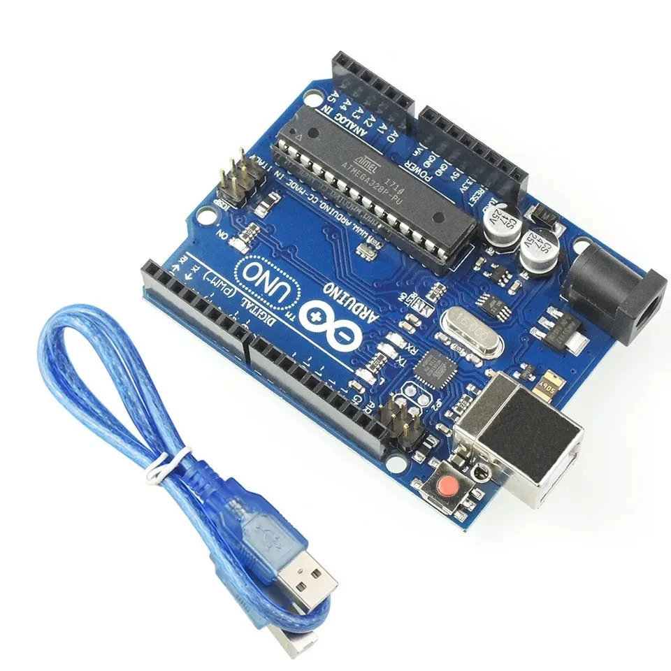
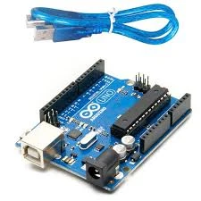
The Arduino Uno R3, built around the ATmega328P microcontroller, is one of the most popular and reliable development boards used worldwide for embedded systems, IoT, home automation, and robotics projects. Known for its stability, ease of use, and strong community support, this board is ideal for students, hobbyists, and engineers. Arduino UNO is a microcontroller board based on the ATmega328P. It has 14 digital input/output pins (of which 6 can be used as PWM outputs), 6 analog inputs, a 16 MHz ceramic resonator, a USB connection, a power jack, an ICSP header and a reset button. It contains everything needed to support the microcontroller; simply connect it to a computer with a USB cable or power it with a AC-to-DC adapter or battery to get started. You can tinker with your UNO without worrying too much about doing something wrong, worst case scenario you can replace the chip for a few dollars and start over again. This version maintains the same pin layout, features, and performance as the official Uno Rev3, making it an excellent choice for learning and building real-world projects — at a much more affordable price. With full support for the Arduino IDE (Windows, macOS, and Linux), and a wide library of example codes, you can get started within minutes — no experience needed. Technical Specification
Arduino Uno Pin DiagramThe Arduino Uno pin diagram provides a clear overview of all the board’s pins. It shows how digital, PWM, analog, power, and communication pins can be used, making it easy to connect sensors, modules, and other components correctly. What is the pinout of the Arduino Uno?
Powering Arduino UnoThe Arduino Uno board can be powered through the USB connection or an external power supply, with automatic power source selection. External (non-USB) power can be provided using an AC-to-DC adapter or a battery. The adapter connects via a 2.1mm center-positive plug to the power jack, while a battery can be connected through the GND and Vin pins of the POWER header. The board operates on an external input voltage range of 6 to 20 volts. For stable and safe operation, a supply of 7 to 12 volts is recommended. Voltages below 7V may cause instability, and voltages above 12V may overheat the voltage regulator and damage the board. Power Pins
How to Program?Programming the Arduino Uno R3 is simple and beginner-friendly. First, install the Arduino IDE from the official website and connect the board to your computer using a USB Type A–B cable. In the IDE, select Arduino Uno under Tools → Board and choose the correct serial port under Tools → Port. You can then write your own sketch or open one of the built-in example sketches to get started. Once your code is ready, click the checkmark (✓) to compile and the arrow (→) to upload it to the board. For projects involving serial communication or debugging, use the Serial Monitor and ensure the baud rate matches your sketch. After uploading, your Arduino Uno R3 is ready to run a variety of projects such as IoT applications, robotics, sensor systems, and home automation. Some notable examples include: |

No review yet!